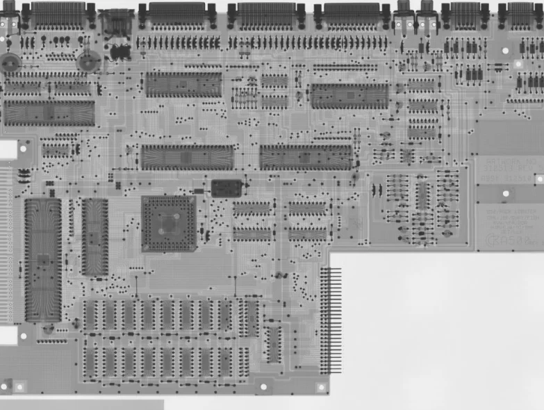
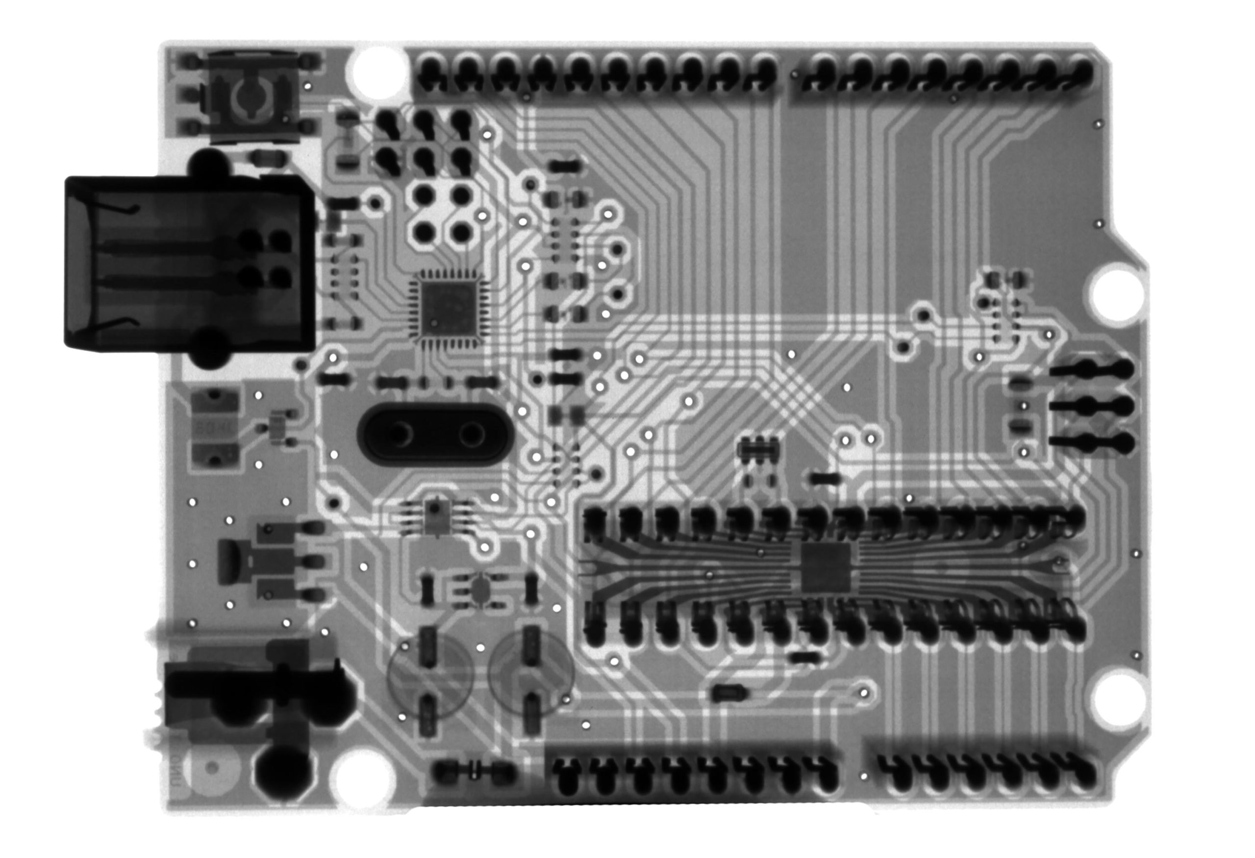
A schematic capture is a digital representation of an electronic circuit.
In electrical and electronic engineering, a schematic capture is the process of converting a circuit diagram into a computer file format that can be simulated or printed. It is also known as electronic design automation (EDA).
What Does Schematic Capture Mean?
Schematic capture is the process of designing a circuit using a graphical representation.
Schematic capture, also known as electronic design automation (EDA), is the process of designing electronic circuits. It involves the creation of a circuit diagram, or schematic, and the subsequent entry of circuit component values and connectivity information.
Schematic capture is a critical first step in the design of any electronic circuit. It allows the designer to clearly visualize the circuit and its component parts, and to verify that the circuit will function as intended.
There are a number of different software packages available for schematic capture, each with its own strengths and weaknesses. Some packages are better suited for simple designs, while others are more powerful and can handle complex designs.
When choosing a schematic capture package, it is important to select one that is compatible with the other software packages that will be used in the design process, such as PCB layout and simulation.
Once the schematic has been created, it can be simulated to verify that the circuit functions as intended. This is an important step, as it allows the designer to test the circuit before it is built.
Simulation can also be used to optimize the design by varying the values of the components to see how the circuit behaves. This is an important step in the design process, as it can save time and money by avoiding the need to build and test multiple prototypes.
Once the schematic is complete and has been verified through simulation, it is ready to be used in the PCB layout process. This is the next step in the design of the electronic circuit.
What Is A Schematic Capture?
A schematic capture is a software program used to create electronic circuit diagrams.
What is a schematic capture?
A schematic capture is a process of converting a physical circuit into a graphical representation. This can be done by hand or using software. Schematic captures are often used in the design and development of electronic devices and circuits.
For example, when designing a new circuit board, engineers will use a schematic capture to create a graphical representation of the board. This representation can be used to verify the design, simulate the circuit, and generate the final layout for the board.
Schematic captures can also be used to document existing circuits. This can be helpful when trying to troubleshoot or modify a circuit. By having a graphical representation of the circuit, it is easier to understand how it works and identify potential problems.
Overall, schematic captures are a valuable tool for anyone working with electronic circuits. They can be used for design, documentation, and troubleshooting.
What Is The Purpose Of Schematic Capture?
The purpose of schematic capture is to create a graphical representation of an electrical circuit.
In the world of electronics, schematic capture is the process of converting a circuit diagram into a format that can be read by electronic design automation (EDA) software. The purpose of this is to create a digital representation of an electronic circuit that can be used to simulate, test, and ultimately fabricate the physical device.
There are a number of reasons why this is important. First, it allows for the quick and easy creation of circuit designs. Second, it makes it possible to test the design before committing to manufacturing. And finally, it provides a way to document the design for future reference.
A real-life example of this would be the design of a printed circuit board (PCB). In order to create a PCB, one must first create a schematic capture of the desired circuit. This can be done using a variety of software packages, but the end result is always the same: a digital representation of the circuit that can be used to test, simulate, and ultimately fabricate the PCB.
What Are The Benefits Of Schematic Capture?
Schematic capture allows for the easy design and modification of electronic circuits.
Schematic capture is the process of converting a circuit diagram into a format that can be read by a computer. This can be used to create a virtual model of the circuit, which can be simulations and analyzed.
There are many benefits of using schematic capture. One benefit is that it can help to reduce the time and cost of designing and debugging circuits. Schematic capture can also be used to create a database of circuit components, which can be used for future reference.
Another benefit of schematic capture is that it can be used to generate PCB layout files. This can be used to create printed circuit boards for prototype or production purposes. Schematic capture can also be used to create 3D models of circuits, which can be used for simulations or visualizations.
A final benefit of schematic capture is that it can be used to document circuits. This can be useful for creating manuals or teaching materials. Schematic capture can also be used to create a bill of materials for a circuit, which can be used for ordering components.
Example:
Let’s say you are designing a circuit that will be used to control a motor. You could use schematic capture to create a virtual model of the circuit, which you could then use to simulate how the circuit will work. This would allow you to test the circuit before you build it, which could save you time and money.
What Are The Best Schematic Capture Tools?
There is no one-size-fits-all answer to this question, as the best schematic capture tool for a given individual or organization will depend on factors such as the specific needs and preferences of the user.
If you’re looking for the best schematic capture tools, you’ve come to the right place. In this article, we’ll provide a step-by-step guide to capture schematics using the best tools available.
First, let’s define what a schematic is. A schematic is a drawing or diagram that shows the layout of an electrical or electronic circuit. Schematics are typically used to communicate the design of a circuit to engineers and technicians.
Now that we know what a schematic is, let’s take a look at the best schematic capture tools.
1. OrCAD
OrCAD is a leading schematic capture tool from Cadence. It’s used by engineers to design and document electrical and electronic circuits. OrCAD offers a comprehensive set of features and capabilities, making it a great choice for a wide range of design projects.
2. Altium Designer
Altium Designer is another popular schematic capture tool. It’s used by engineers to design, simulate, and validate electrical and electronic circuits. Altium Designer offers a wide range of features and capabilities, making it a great choice for a wide range of design projects.
3. KiCad
KiCad is a open-source schematic capture tool that’s popular among hobbyists and professionals. It’s used to design, simulate, and document electrical and electronic circuits. KiCad offers a wide range of features and capabilities, making it a great choice for a wide range of design projects.
4. Eagle
Eagle is a popular schematic capture tool from Autodesk. It’s used by engineers to design, simulate, and document electrical and electronic circuits. Eagle offers a wide range of features and capabilities, making it a great choice for a wide range of design projects.
5. Fritzing
Fritzing is a open-source schematic capture tool that’s popular among hobbyists. It’s used to design, simulate, and document electrical and electronic circuits. Fritzing offers a wide range of features and capabilities, making it a great choice for a wide range of design projects.
Now that we’ve looked at the best schematic capture tools, let’s take a look at a real-life example.
For this example, we’ll use OrCAD to capture a schematic of a simple circuit.
1. To get started, launch OrCAD and create a new project.
2. In the project, create a new schematic.
3. In the schematic, add the following components:
– A power supply
– An LED
– A resistor
4. Connect the components together according to the following schematic:
5. Save the schematic and close OrCAD.
In this example, we’ve used OrCAD to capture a schematic of a simple circuit. This is a great way to get started with OrCAD and learn how to use its features and capabilities.
FAQ
How Do I Create A Schematic Capture?
How Do I Use Schematic Capture?
What Are Some Tips For Creating A Good Schematic Capture?
1. Make sure your schematic is clear and easy to read. This means using clean and consistent lines, and labelling everything clearly.
2. Use standard symbols and abbreviations where possible, to make your schematic easy to interpret.
3. Annotate your schematic fully, to explain the purpose of each component and connection.
4. Make sure your schematic is electrically correct, by checking the connections and component values against a reference design or simulation.
How Can I Improve My Schematic Capture Skills?
What Are Some Common Mistakes Made During Schematic Capture?
Conclusion
Schematic capture is a process of designing and documenting an electronic circuit using a specialized drawing tool. The output of the schematic capture process is a schematic diagram, which can be used to manufacture the circuit or to simulate its behavior.
If you still have any questions about what schematic capture means, feel free to leave a comment below.
Author
-
I'm Shahrear, a Designer Lead who loves electronics. Since 2003, I’ve been traveling and living all over the world. I love breaking down complex concepts in electronics and presenting them to others in an approachable way. I think that the language used in most books about electronics is hard for people who don't already know about electronics to understand. I want that to change. So, I've started blog where I talk about everything on electronics for people who are just starting out.
View all posts


